Introduction
Choosing the right UVC LED package size affects more than component placement; it also influences optical output requirements, PCB design, and the complexity of the finished module. For structural engineers, PCB designers, and module manufacturers, the decision between 3535 and 6565 packages requires balancing available space, electrical specifications, optical coverage, and thermal design constraints. This guide explains how to compare these package options, evaluate their integration requirements, and select suitable devices for reliable, cost-effective UVC LED systems.
3535 vs. 6565 UVC LED: Footprint, Power & Selection Trade-Offs
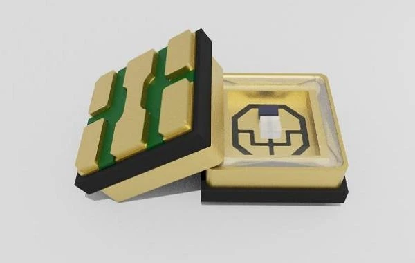
When comparing different UVC LED package types, engineers should evaluate 3535 and 6565 SMD UVC LED options based on their actual model specifications, nominal footprints, and application requirements.
Choose 3535 UVC LED Packages: Space-Constrained Designs
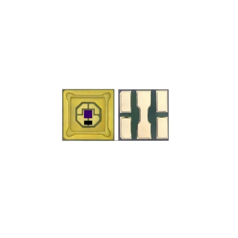
A 3.5 × 3.5 mm package occupies a nominal footprint of 12.25 mm², making it worth evaluating for compact water-treatment equipment, embedded appliances, and portable disinfection devices where PCB space is limited.
Choose 6565 UVC LED Packages: Higher Optical Output Requirements
A 6.5 × 6.5 mm package occupies 42.25 mm², while the LM2IQUB model is listed with 650–1000 mW optical output and a 600 mA forward current, making it a candidate for applications requiring higher output from an individual emitter.
Compare Complete Models, Not Just Package Sizes
The LS4AQHB 3535 model is with 50–175 mW optical output at 350 mA, illustrating why buyers should compare wavelength, forward voltage, current, optical power, and radiation angle rather than assuming that package dimensions alone determine performance.
How Package Size Shapes PCB Layout and Mechanical Integration
The physical dimensions of a UVC LED influence PCB placement, enclosure design, and assembly clearance, so engineers should evaluate the complete installation footprint rather than the package body alone.
PCB Footprint & Component Spacing
Although a 3535 package occupies 12.25 mm² compared with 42.25 mm² for a 6565 package, the final PCB area must also accommodate solder pads, electrical routing, driver components, insulation requirements, and spacing between adjacent emitters.
Enclosure Height & Assembly Clearance
Structural engineers should check package height, optical window thickness, mounting features, manufacturing tolerances, and service access against the available enclosure dimensions before approving a design for tooling or production.
Single High-Power LED vs. Multiple Smaller LEDs
A single high-output 6565 device may simplify emitter placement, whereas multiple 3535 devices can distribute irradiation across a larger target area, but the preferred configuration depends on driver-channel requirements, optical uniformity, PCB complexity, and installation constraints.
Plan Optical & Electrical Interfaces Together
PCB designers should coordinate LED placement with the optical window, reflector or lens assembly, connector positions, and driver circuitry to prevent mechanical interference and avoid costly layout revisions during prototype development.
How Package Selection Affects Optical Coverage and System Performance
Package selection affects how engineers arrange emitters and optical components, but the finished system's performance must be evaluated using measured optical conditions rather than package dimensions alone.
Match Radiation Angle to the Target Area
Available 30°, 60°, and 120° radiation-angle options can support different optical layouts, with the appropriate choice depending on source-to-target distance, required coverage, optical components, and the geometry of the treatment chamber.
Evaluate Optical Power at the System Level
Rated LED optical power describes the emitter's output under specified test conditions, whereas irradiance at the target and delivered UV dose depend on optical losses, distance, exposure time, and the arrangement of the light sources.
Account for Application-Specific Operating Conditions
Water-treatment designers must also evaluate flow rate, water transmittance, reactor geometry, and exposure distribution, while surface-disinfection designers should consider shadowing, target distance, and the uniformity of irradiation.
Validate the Complete Optical Assembly
Engineers should measure irradiance across representative target locations using the actual PCB, optical window, and enclosure, then confirm that the system meets its required treatment performance under realistic operating conditions.
For additional background on packaged-device construction and optical design considerations, see this guide: How Are UVC LEDs Packaged? From Bare Chip to Packaged LED, which covers the underlying packaging technology rather than the system-level selection decisions discussed here.
Thermal Design & Total Integration Cost
A suitable package must operate within the selected LED's electrical and thermal limits, so procurement teams should assess the complete module design instead of treating package size as a reliable indicator of cooling capability.
1. Assess the Complete Thermal Path
Review the selected model's thermal resistance, recommended operating conditions, solder-pad design, PCB material, interface materials, and heatsink arrangement to determine whether the assembled device can maintain its specified operating limits.
2. Compare Total Module Cost
Include the LED price, driver circuitry, PCB materials, thermal components, optical parts, assembly processes, and testing requirements when comparing a single high-output device with an array of smaller emitters.
3. Evaluate PCB Material Requirements Against Actual Loads
Do not assume that every 3535 device requires an aluminum nitride substrate or that a larger 6565 package automatically provides better heat dissipation, because the appropriate board construction depends on the model, power dissipation, thermal path, and operating environment.
4. Validate Performance Before Freezing the BOM
Test representative samples at the intended drive conditions and verify thermal stability, optical output, and mechanical compatibility before approving the final bill of materials for volume production.
For a deeper explanation of heat transfer, junction temperature, and their effects on optical output and service life, pay attention to our guide: How Thermal Management Affects UVC LED Output and Lifetime rather than duplicating its underlying thermal theory here.
A Practical UVC LED Package Selection Checklist for Buyers
Before requesting quotations, engineering and procurement teams should convert their design requirements into a consistent specification that suppliers can use to recommend compatible devices.
1. Define the Available Space
Specify the maximum PCB footprint, mounting height, component spacing, optical-window dimensions, and enclosure restrictions so the supplier can identify physically suitable package options.
2. Specify the Optical Target
State the required wavelength, target optical output, radiation angle, treatment area, and operating conditions to avoid selecting a device solely because its package is compact or its rated output is high.
3. Verify Electrical & Thermal Limits
Confirm forward current, forward voltage, recommended operating conditions, PCB requirements, and thermal-interface constraints against the selected model's documentation.
4. Request Model-Specific Documentation
Obtain package drawings, recommended pad layouts, electrical and optical specifications, and relevant reliability information before committing to a PCB layout or production tooling.
5. Test Representative Samples
Evaluate the selected device on the intended PCB and inside the actual enclosure, recording electrical behavior, thermal stability, optical distribution, and compatibility with the complete module.
6. Confirm Production Requirements
Discuss target order quantities, sample availability, product consistency, customization needs, and delivery schedules before finalizing the purchasing plan.
UVLEDTEK supports UVC LED package selection through its range of 3535 and 6565 devices, allowing buyers to compare model-specific optical and electrical specifications for their applications. Its product offering also provides a starting point for evaluating custom emitter configurations against PCB space, optical requirements, and module integration constraints.
Conclusion
Selecting the right UVC LED package size requires balancing available space, optical output, electrical requirements, thermal design, and total module cost rather than prioritizing the smallest footprint or highest rated power alone. Comparing complete 3535 and 6565 model specifications and validating representative samples helps engineering teams reduce integration risks before committing to production. Review the available UVC LED package options and submit your target wavelength, PCB dimensions, optical requirements, and operating conditions to request a suitable device recommendation.
Contact Us for More UVC LED Details
FAQ
Q: Can I Replace a 3535 UVC LED With a 6565 Model on the Same PCB?
A: Not without checking the footprint, pad layout, electrical ratings, thermal path, and optical alignment, because different package dimensions do not guarantee drop-in compatibility.
Q: What Should I Send a Supplier When Requesting UVC LED Samples?
A: Provide your application, available PCB space, target wavelength and optical output, drive conditions, radiation angle, operating environment, and expected order quantity so the supplier can recommend suitable models for evaluation.